



 is assembled by joining separate metallic sections to create a single working component. This approach can support custom configurations, large dimensions, and integrated features that would otherwise require extensive machining. Its success depends on suitable joint design, compatible materials, controlled welding, dimensional correction, and inspection appropriate to the application. ## When a Welded Design Makes Sense Welded construction is worth considering when a shaft has a complex profile or includes a large flange, hub, sleeve, or other attached section. It may allow different stock sizes to be combined, reducing the need to remove large amounts of material from a single billet. It can also be useful when a component must be manufactured in sections because of transport, handling, or equipment limitations. In repair work, a qualified procedure may permit replacement of a damaged section, although the feasibility depends on the original material and service conditions. The decision should be based on engineering and lifecycle cost. Welding is not automatically cheaper or stronger than machining a one-piece shaft. ## Joint Location and Load Paths The joint must transfer the forces that act through the shaft. These may include torsion, bending, axial force, and cyclic loading. The weld configuration and size should be designed for the expected load combination. Joint location deserves particular attention. Placing a weld near a keyway, bearing shoulder, or region of high bending stress may combine several stress concentrations. Where possible, the joint should be positioned in a region with more favorable loading and enough space for inspection and finishing. A smooth external profile is also important. Abrupt changes in diameter or weld reinforcement can interfere with bearing fits and create local stress concentrations. ## Material Compatibility and Welding Procedure The parent materials must be suitable for joining by the selected process. Their chemistry, thickness, hardenability, and heat-treatment condition influence weldability. Filler material should be selected to provide appropriate mechanical and corrosion properties. Depending on the steel grade and section thickness, preheating or controlled cooling may be required. Some applications may also require post-weld heat treatment to manage residual stress or achieve specified properties. The process should be documented in a qualified welding procedure. Heat input must be controlled. Excessive heat can increase distortion and alter the material's microstructure, while insufficient heat or poor technique can produce incomplete fusion or other defects. ## Alignment and Distortion Management A shaft must remain sufficiently straight and concentric for its bearings and connected components to operate correctly. Welding causes localized heating and cooling, which can pull sections out of alignment. Fixtures and a planned welding sequence help control movement. The completed component may need straightening, stress relief, or machining. These operations should be specified in advance so that the design includes enough material and suitable reference surfaces for final correction. ## Machining and Surface Finishing After welding, turning can establish the final diameter and profile. Grinding may be needed for bearing journals or precision interfaces. Keyways, threads, splines, and holes may be machined at the appropriate stage. The manufacturing plan should identify which features are finished before welding and which are completed afterward. Machining critical surfaces too early may allow subsequent distortion to make them unusable. Conversely, some features may be difficult to access once the assembly is complete. ## Inspection and Quality Assurance Visual inspection is useful for identifying surface irregularities, but internal weld quality may require additional examination. Depending on the application, magnetic particle, penetrant, ultrasonic, or radiographic testing may be specified. Dimensional inspection should verify straightness, runout, concentricity, overall length, and critical interface locations. Material traceability, weld procedure records, and operator qualifications may be required for demanding applications. ## Where Specialized Welded Shafts Are Used Custom welded shafts may be found in industrial rollers, large drive assemblies, material-handling equipment, processing machinery, and specialized production systems. Their use is appropriate only when the design and quality plan address the consequences of joint failure. ## Conclusion Welded shaft construction gives manufacturers flexibility when a one-piece component is difficult or uneconomical to produce. Dependable results require careful load-path design, compatible materials, qualified welding procedures, distortion control, post-weld machining, and suitable inspection. When these elements are planned together, welded construction can support specialized mechanical applications without compromising the required level of reliability.](https://webtoonxyz.co.uk/wp-content/uploads/2026/11/pump-shaft-article-1.jpg)
Key Design Considerations for a High-Performance Servo Motor Shaft
A high-performance servo system is expected to respond quickly, position accurately, and maintain stable motion as its load changes. These requirements place demanding expectations on the mechanical components connected to the motor. Control electronics and feedback devices may define the commanded movement, but the shaft must transmit that movement to the load without introducing unacceptable deflection, vibration, or alignment error.
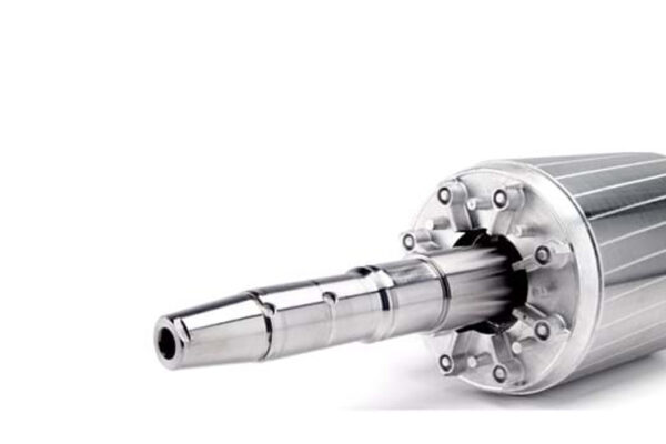
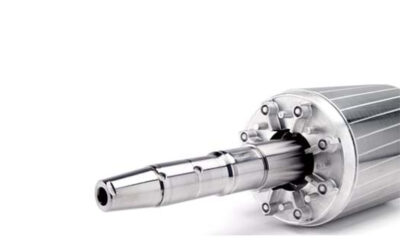
The Servo Motor Shaft is a critical part of this mechanical path. Its design affects torsional stiffness, runout, bearing support, coupling behavior, and the dynamic response of the complete axis. For this reason, shaft specification should begin with the motion system’s performance requirements rather than simply copying dimensions from a general-purpose motor.
Torsional Stiffness and Positioning Accuracy
When torque is applied, every shaft twists to some degree. The amount of angular deflection depends on material properties, shaft length, cross-sectional geometry, and applied torque. In a precision motion system, excessive twist can create a difference between the motor rotor’s position and the driven load’s actual position.
A shorter or larger-diameter shaft generally provides greater torsional stiffness, although the design must also account for mass and inertia. The coupling, gearbox, belt, and driven mechanism contribute additional compliance. Engineers should therefore evaluate the entire transmission chain.
Dynamic Behavior and Resonance
Servo systems frequently accelerate and decelerate rapidly. These changes can excite natural frequencies in the shaft and connected components. If a control command repeatedly excites a mechanical resonance, the system may develop vibration, noise, or extended settling time.
Shaft stiffness, coupling characteristics, mounting rigidity, and load inertia all influence the dynamic response. Mechanical design and servo tuning should be considered together. Increasing stiffness may help, but a change in one component can shift the system’s resonant behavior and require control adjustments.
Runout and Concentricity
Runout is the variation in a shaft surface’s position as it rotates. Excessive runout can cause cyclic displacement, vibration, and uneven loading. Concentricity between bearing journals, coupling seats, and other functional surfaces is particularly important in precision equipment.
Bearing seats should meet the specified diameter, roundness, and surface-finish requirements. Shoulder faces must be square enough to locate components correctly. Poor machining or assembly can undermine the accuracy expected from a high-resolution encoder and servo drive.
Material Selection
Shaft materials must provide suitable strength, stiffness, fatigue resistance, and machinability. Carbon and alloy steels are common choices for many servo motors. Stainless grades may be appropriate in applications involving moisture, cleaning, or corrosive exposure.
Material selection should reflect the actual torque and bending loads, not simply a preference for maximum hardness. Heat treatment may improve selected properties, but it must be controlled to avoid distortion or brittle behavior. Any surface treatment should preserve critical dimensions and compatibility with bearings and couplings.
Coupling and Interface Design
The shaft may connect to a load through a keyed, clamping, splined, threaded, or specialized interface. A clamping coupling can provide a compact connection, while a keyed arrangement offers positive torque transfer. The correct solution depends on torque, speed, backlash requirements, shaft diameter, and assembly access.
A flexible coupling can accommodate limited misalignment, but it should not be used to hide poor installation. Excessive flexibility may reduce torsional stiffness and affect response. The coupling must be selected as part of the motion system.
Bearing Loads and Shaft Support
Servo motor bearings have defined radial and axial load limits. A heavy pulley, belt tension, or overhung coupling can impose forces that exceed these limits if the shaft arrangement is not properly designed.
Where external loads are significant, a separately supported transmission may be needed. The shaft extension, bearing spacing, and mounting structure should be reviewed together to limit deflection and protect the motor bearings.
Manufacturing and Verification
Precision turning and grinding may be required to achieve critical diameters and surface finishes. Inspection should include runout, straightness, concentricity, shoulder position, and interface dimensions. High-speed assemblies may also require balancing.
Testing should reflect the intended duty. A shaft that passes static dimensional inspection may still need dynamic verification as part of the assembled motor or machine.
Conclusion
A high-performance servo motor shaft must balance stiffness, accuracy, strength, inertia, and connection reliability. Its design should reflect the full motion system, including bearings, couplings, feedback, and load characteristics. Careful engineering and inspection help preserve positioning accuracy, control vibration, and support repeatable motion over the machine’s service life.